
The trip's timing is the first witness
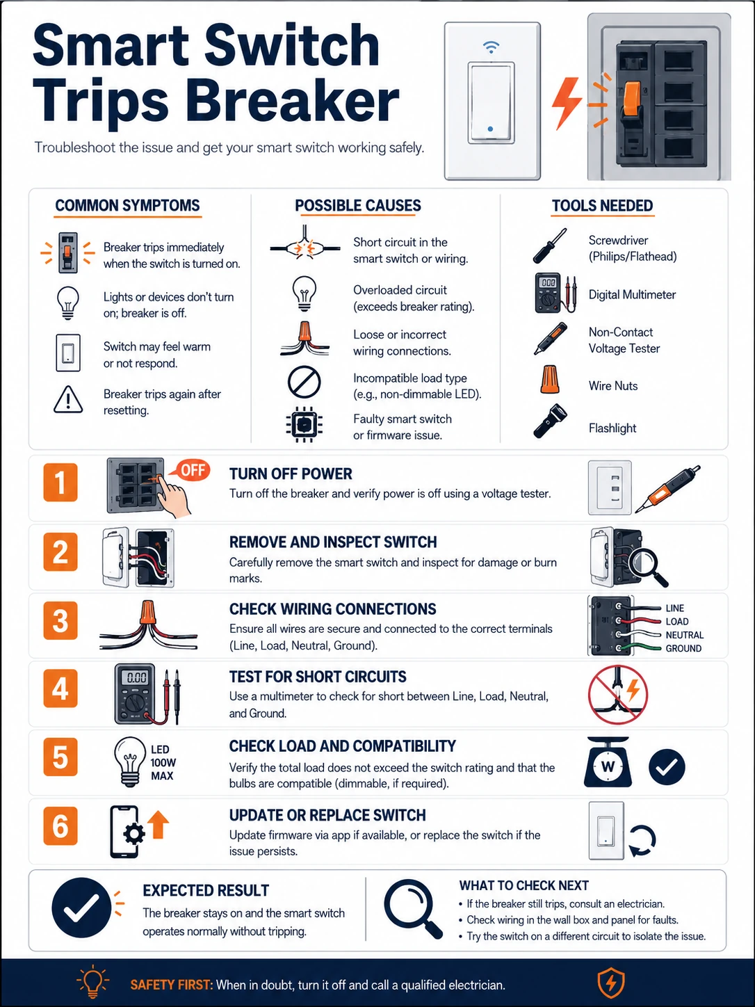
When the trip happens narrows what went wrong. Instantly at breaker-reset, before anything is touched: a hard short — line landed on neutral or ground, or a stray copper strand bridging terminals in the crowded box. Only when the switch is operated: the fault sits on the switched leg — the LOAD wiring or the fixture itself. Seconds-to-minutes after the light comes on: thermal or overload territory — too much load, or inrush from many LED drivers exceeding what the switch tolerates.
The second principle is restraint: every additional reset into a hard short stresses the wiring and erases nobody's confusion. One trip is a data point; five trips is damage. Photograph, label, stop, and let the diagnosis proceed de-energized under someone qualified.
Prepare before testing
- Phone camera — terminal-by-terminal photos before anything moves are the best evidence in the box
- Masking tape and pen — label each conductor as found — colors alone mislead in older installations
- The switch's wiring diagram — L, N, LOAD and traveler assignments per the maker, not per assumption
- A qualified electrician — the person who verifies dead, identifies conductors properly, and corrects the wiring
Repeated resets into a fault are not diagnosis, they are wear on safety equipment and wiring. After the second trip, the circuit stays off until verified dead and inspected by someone qualified. This entire fault class is electrician territory; the homeowner's role is evidence and history.
Check these areas first
- Line-to-neutral or line-to-ground misconnection. the classic instant trip after L/N/LOAD were guessed from wire color
- Stray strand or long-stripped conductor. one whisker of copper touching the box or a neighboring terminal
- Multiway wiring misread. traveler and common conductors in two-way circuits misassigned to smart-switch terminals
- Damaged insulation pinched in the box. the switch's bulk pressing conductors against sharp box edges as it seated
- Overload or inrush beyond rating. many LED drivers on one switch: steady watts within spec, but switch-on surge far beyond
Diagnostic procedure
Classify the trip, preserve the scene, then support the electrician's conductor-by-conductor verification — and close with the load arithmetic that prevents round two.
Classify the trip by timing
Reconstruct precisely: does the breaker (or RCD) trip the instant it is reset, only when the switch is toggled, or some time after the light runs? Note also which protective device acts — overcurrent breaker versus residual-current device points at short versus leakage. This classification is the single most useful sentence you will give the electrician.

Preserve the scene after the second trip
Stop resetting. Photograph the switch's terminals as wired, each conductor's routing in the box, and any labels from the old switch. Tape-label conductors before anything is disturbed. If the old dumb switch's wiring was photographed at removal, gather those photos too — the before/after pair often contains the whole answer.

Have the circuit verified dead and conductors identified
The electrician isolates, proves dead with a tested verifier, then identifies each conductor properly — line, neutral, switched load, and any travelers — by testing, not color folklore. Older boxes and previous DIY generations make color assumptions the leading source of exactly this fault.

Inspect the physical dress of the box
With conductors known, the box is inspected for the mechanical causes: stray strands outside terminals, insulation stripped too long leaving bare copper exposed, conductors pinched between the switch body and box edge as the switch was seated, and terminal screws torqued onto insulation instead of copper. Each is corrected and the box re-dressed with room for the switch.

Split the circuit to isolate switch versus load
If the wiring dresses clean, the electrician tests in halves: switch energized with the load leg disconnected (switch electronics proven alone), then the load reconnected. A trip only with load reattached moves the fault downstream — into the fixture, its driver, or the cable run — and out of the switch's box entirely.

Do the LED load arithmetic
For delayed or on-switch-on trips: sum the fixtures' real watts, then check the switch's LED-specific rating — makers derate LED loads to a fraction of the resistive figure because driver inrush current at switch-on dwarfs steady draw. Many drivers on one switch may need a lower count, an inrush-rated switch, or splitting across circuits.

Why twenty LED drivers can trip what two hundred watts never would
An LED driver's first milliseconds look nothing like its steady state: input capacitors charge in a surge that can reach tens of times the running current. One driver's blink of inrush is absorbed easily; a whole room of downlights switching as one stacks those surges into a spike that welds relay contacts, nuisance-trips breakers, and explains switches that die young on paper-legal loads. The remedies are specified, not improvised: switches rated for capacitive/LED loads with inrush figures published, loads split across switches, or soft-start modules where a large bank must switch together. When a trip happens only at switch-on with everything wired correctly, this arithmetic is almost always the verdict.
Why the photos matter more than the theory
Electrical faults reward evidence over recollection. The terminal photos taken before disturbance, the labeled conductors, the noted trip timing — these compress the electrician's diagnostic time from an hour of rediscovery to minutes of confirmation, and they protect against the second-visit scenario where a re-wired box trips differently and nobody remembers the original state. The same habit applies forward: photograph the corrected wiring at closure, tape the circuit's map inside the faceplate, and the next switch upgrade in that box starts from knowledge instead of archaeology.